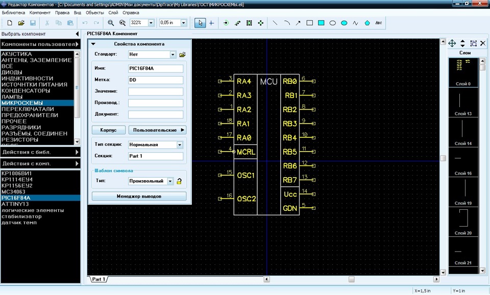

I am used to the traditional use of busses to carry signals that are homogeneous except in magnitude, such as data lines, address lines, IRQs, etc. This doesn't strictly answer the question exactly as stated, so I'm not going to mark this as the answer, but I'll post what I've found as a satisfactory approach.īasically, I adapted my style a bit more to the capabilities and omissions of the program. 12-pin header- that spans a few pages, and you can connect to that connector instead. Maybe you can have connector netport- I.e. It took me less than a minute.) The positive is that you can create your own custom netports. Unfortunately you'll have to at least once create it. (Not shown is the label of the netport, which is both Net 0.)Īs long as you change the names of the netport, you can have as many as you'd like. When highlighting the trace to one of the resistors connected to SIGNAL, the entire port is highlighted. The two SIGNAL ports connected to two different resistors, and a CLOCK port connected to a third resistor. For instance, I have two different types of connector: SIGNAL and CLOCK. Make sure to change the type of your connector to the same port that you want. In your schematic editor, add your components. Make sure that the Part Type is Net Port. In component editor, preferably Discrete Schematic, Component > Add New to Library.ĭraw a port connector that you're use to.


 0 kommentar(er)
